Shenzhen Grande Electronic Linkedin Page
Shenzhen Grande Electronic Co., Ltd logo
E-mail us for a Quote:
sales88@greattong.com
Call us now:
+86-755-83261869

Technical Article


How to Export Gerber Files from Eagle

Time:2017-05-25 14:07:12 Click:

The purpose of this document is to assist Shenzhen Grande’s clients in the process generating Gerber files using the software suite known as Eagle. Shenzhen Grande asks that its clients supply their PCB design files in this format because Gerber is the industry standard file type, and is therefore easily recognized and processed by our manufacturing equipment. We at Shenzhen Grande recognize that this procedure may not be familiar to all of our clients, and so we will proceed with a step-by-step description in the following section.


Generating Gerber Files
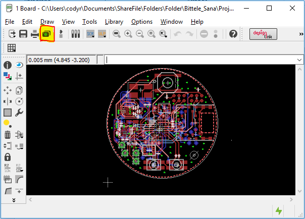
This guide assumes that you have finished designing your PCB within Eagle, and that you have a stored file in the .brd format. We must extract Gerber files from the .brd file using Eagle’s Cam Processor software. Steps for this extraction are outlined below: 

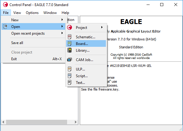
1. Open the control panel for Eagle

control-panel-for-Eagle


2. Select File -> Open -> Board, and navigate to the .brd file that you would like to work with


3. A window showing the PCB layout should now appear, as shown below:

PCB-layout


4. Select the camera icon from the top ribbon (highlighted below), or select File -> Cam Processor 


5. A new window will appear for the Cam Processor. In this window, select Open -> Job, as shown: 

Select Job


6. Select gerb274x-mill-drill.cam. This job file is set up for a 2-layer board, but the following examples show how to specify additional layers with the job if you so require. 

7. In the Output section of the Cam Processor window, select the File button, and navigate to the location in which you would like to store the converted Gerber files. Choose a file name for the layer, for example: the Component Side tab could have the file name “TopCopper.cmp” 

Component Side tab


8. If the board is greater than 2 layers, we must use the Add button in the bottom-right corner of the window to duplicate one of the existing copper layers, and modify its settings. 

duplicate existing copper layers


9. Re-name this layer in the Section field of the Job section, then choose the copper layer that it represents from the scrolling list at the far right of the window. For a regular inner copper layer, you should only need to select the copper layer itself (Route2 in above picture), the Pads, and the Vias. 

10. Now for the drill files; first choose the tab called “Drill PAD/VIA”, and ensure that the “Pads” layer and the “Vias” layer are selected (these are not selected by default). Also scroll down to ensure that the “Drills” layer is selected, although this one should be selected by default. 

Drill PAD-VIA


11. Next, choose the tab called “Drill HOLEs”, and scroll down in the layers list to ensure that both the “Drills” layer and the “Holes” layer are selected. (Holes is selected by default, but not Drills) 

Drill HOLEs


12. Once you have specified File destinations for each of the tabs within the Cam Processor window, select the Process Job button at the bottom of the window. 

13. Check the file path that you specified in step 7 to ensure that your Gerber files have been generated successfully. If you have access to a Gerber Viewer software, you can use it now to verify that the contents of your design files were preserved through the conversion procedure.


Drill File Secondary Option
If you already have the Gerber files, and simply need to export your PCBs drill files on their own, then worry not! The process for this is actually quite straightforward; it incorporates only four (4) steps: 

1. From the Board view of your .brd file, select File -> Run ULP

Run ULP


2. Choose the file called drillcfg.ulp

drillcfg.ulp


3. Select the measurement units for your drill file. These should match with the measurement units you specified during the design phase for this board. Select Ok. 

measurement units


4. Select Ok on this screen. Do not edit the text in this window unless you are absolutely certain of what you are doing.

edit drill configuration


5. Choose a file location for your drill files, and that’s it, you have successfully exported your Gerber files! 

This guide’s aim has been to describe the procedure for generating Gerber files as simply and completely as possible. If you still find yourself unclear on any part of the process, please do not hesitate to contact a member of the Shenzhen Grande sales team by sending an email to sales88@greattong.com. We are happy to help with any of your queries.

Previous:How to Create a Reflow Profile for a PCB?

Next:How to Get a Quote for Turnkey Circuit Assembly?


Request an Official Quote

Questions

E-MAIL

File Upload

Upload a list of files

    Please upload your Gerber files and BOM. You can upload an unlimited number of files as long as the total size of all files does not exceed 20 MB. To ensure you receive your official quote in less than 24 hours, please include the quantity of circuit boards for which you would like a quote.

    If you require that we sign a Non-Disclosure Agreement (NDA), please send it to us prior to sending your files and we will be happy to accommodate.

     
    Home About Us Services Quality Pb-Free News Contact Us


    Copyright ® 2017,Shenzhen Grande Electronic Co., Ltd. All Rights Reserved. English 中文站 Sitemap