What is PCB project in Altium Designer?
In Altium Designer, a project includes all the files associated with each other and design-related settings. A project file, such as xxx.prj PCB, which is a ascii text file that includes files in the project and related settings for output, such as print settings and cam settings. Documents unrelated to engineering are called "free files". Files associated with schematics and target output are added to projects, such as PCB fpga, embedded (vhdl) and libraries. When the project is compiled, design verification, simulation synchronization and alignment will be carried out together. Any changes to the original schematic or PCB will be updated at compile time.
All types of projects are created in the same way. This paper introduces the creation process of PCB project, first creates the engineering file, then creates a new schematic diagram and adds it to the newly created project, and finally creates a new PCB, which is added to the project just like the schematic diagram.
How can we create a PCB project?
1.Selecting file > new > project > PCB project, or click blank project (PCB). In the new option in the files panel If this option is not displayed on the interface, select files from system. You can also select printed circuit board design, in the pick a task section of the home page of the Altium Designer software and click new blank PCB project.
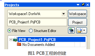
2.Displaying the projects panel box on the screen. The new project file PCB_project1.prj PCB is already listed in the box and does not include any files, as shown in figure 1.
3.Renaming the project file (with the extension .prj PCB) and select file > save project as. Save where you want to store, enter the project name multivibrator.prj PCB in file name and click save to save.


