What is the relay?
The complete name of the relay is an electromagnetic armature relay, which is separated from the solid-state relay. The full name is not commonly used, and is usually referred to as an abbreviation. Some people refer to relays as motor relays, but when it comes to the relay, it is known that they are not solid state relays.
What is the function of the relay?
The function of the relay is to enable one signal or pulse to turn another current on or off. Typically, relays use a lower voltage or current to control higher voltages or currents. These low voltage/current signals can be activated through smaller, less expensive switches and carried to the relay via small gauge wires. The relay can therefore be used to control a large current. For example, in an automobile engine, a light is sent to the relay next to the starting device while the ignition switch is turned on.
Although solid-state switching devices are faster and more stable, relays still have some advantages. Relays can handle double-throw multiple-pole switches and are less expensive to handle high voltages or currents. At the beginning of the bipolar transistor chapter, there are relays, solid state relays and electricity. Comparison of the pros and cons of the crystal.
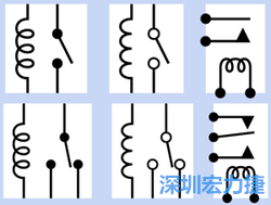
The picture on the right is a single-cut (top) and double-cut (lower) relay diagram on the circuit diagram. The appearance of the coil and the contact symbol may be different, but the functions will not be different.
What is the principle of operation?
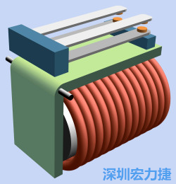
The relay contains a coil, a set of armatures and at least one pair of contacts. The current flows through the coil. The coil acts like an electromagnet, which generates a magnetic field. The magnetic field thus pushes the armature. The shape of the armature resembles a rotating bracket and is released (or sucked). Combined two contacts. For easy identification, the armature is usually painted green, the coils and contacts are red and orange, the two blocks in blue are insulating, and the one on the left is used to support the contacts.
The one on the right will pick up the joint when the armature moves due to the change of the magnetic field of the coil. The line between the contact and the coil is ignored for the sake of simplicity.
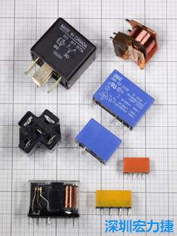
The picture on the right shows a number of different small relays that correspond to different voltage and current usage requirements. In the upper left corner of the figure is a 12V DC relay, which needs to be plugged into the socket below it; the top right is a 24V DC single-pole double-cut relay. Due to the exposed coil and contact, this relay must be dry. A clean environment can be used. And continue to look down the picture, the four relays installed in the color plastic box can switch the current of 5A at 250V AC voltage, the current of switch 10A under 120V AC voltage, and the current of switch 0.6A under 125V AC voltage. , the current of switch 2A under 30V DC voltage. The two blue relays have 12V DC coils, while the red and yellow relays contain 5V coils. These relays are non-latching. The only exception is the yellow one, which is a latched relay. There are two coils inside. In the lower left corner is a 12V DC relay, which is housed in a transparent box. According to the specification, it can switch 5A current in 240V AC or 30V DC.
Relays are represented in the same circuit diagram as switches, and SP, DP, 3P, and 4P represent single, double, triple, or quadrupoles respectively (relays that are more than four poles are not common). ST and DT represent single-cut or double-cut switches. Usually, these abbreviations will be combined, such as 3PST or SPDT. In addition, Form A (meaning usually open), Form B (meaning usually closed) and Form C (representing double cut) are also common. The numbers in front of the letters usually represent the number of electromagnetic poles. Therefore, "2 Form C" means a bipolar double-cut relay.
What are the basic forms of relays?
There are two basic forms of relays: latching and nonlatching.
Non-latching relays, also known as single side stable relays, are the most common. They are like temporary switches (or buttons). When the relay power is cut off, the connector bounces back to the original. The default state. This is important in some applications, as long as the power supply disappears, the relay will return to its original state. Conversely, the latched relay has no preset state, and almost has double-cut contacts. It can stay on either side without using power. This relay only needs a short pulse to change the status quo. Among the terms, this is similar to the flip-flop effect. .
In the case of a single-coil latched relay, the polarity of the applied voltage will determine which pair of contacts will be closed; in a two-coil latched relay, the second will move the armature between the two states.
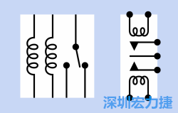
The double-coil latched relay is shown in the circuit diagram as shown in the right. In some circuit diagrams, the coil and switch current directions are not clearly expressed, so it is necessary to go back and read the manufacturer's instructions or directly on the relay. Apply voltage and arbitrarily select two connectors to test.
How many kinds of DC relays?
There are three kinds of DC relays: in the neutral relay, the polarity of the DC power is not important. The relay can maintain good function regardless of the direction of the current. One of the polar relays has a diode and a coil in series, blocking from a certain The current in one direction; the biasing relay has a permanent magnet near the armature that boosts the efficiency when the current passes in a certain direction, but it has a suppressing effect when the current passes in the opposite direction. These terms are not necessarily used in the manufacturer's specifications, but will indicate whether the relay coil is affected by the polarity of the direct current.
Incidentally, all relays can be used to switch AC power, but only AC relays can use AC power as the current of the coil.