It is well known that SMD component is one of the materials that have more contact in SMT Repair. That’s to say, in SMT Assembly, SMD components often need to be replaced from time to time. It seems very simple to replace SMD components, but there are still plenty of tricks in it. If you do not pay attention, it is still pretty troublesome to operate. In order to ensure product quality, we need to replace SMD components in strict accordance with relevant requirements.
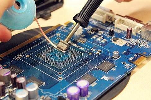
First of all, what we need that is to prepare an electric soldering iron which is used to connect the ground as well as temperature can be controlled before performing the operation of replacing the SMD components in SMT repair. Apart from that, the width of the soldering iron tip must match the size of the metal end face of the SMD component, and the soldering iron need to be heated to 320℃. In addition to the electric soldering iron, you also need to prepare basic tools such as tweezers, tin strips, fine low-temperature rosin, and soldering wire.
When replacing SMD components, you can directly put the heated soldering iron tip on the upper surface of the damaged component, and then wait until the solder on both sides of the SMD component and the adhesive under the component are melted by high temperature, you can use tweezers directly removed the damaged component. After removing the damaged component, it is also necessary to use a de-tin strip to suck up the remaining tin on the circuit board, and then wipe the adhesive and other stains on the original pad with alcohol.
PCB board is under assembly, usually only a proper amount of solder is applied to one pad on the circuit board; Then using tweezers to place the component on the pad. In order to quickly heat the tin on the pad, the molten tin contact SMD component need to be placed on the metal end, but there is another point that need special attention, do not let the soldering iron tip directly touch the component.
Generally, as long as one end of the newly replaced SMD component is fixed, the other end can be soldered. It is necessary to heat the pad on the circuit board and add an appropriate amount of solder to make the pad and the component end surface form a bright arc. In the meanwhile, it should be noted that the amount of solder can not be put too much, otherwise the molten solder will flow under the component and cause the pad to short-circuit. Just like the other end of soldering, the remaining end can only allow the molten tin to dip into the metal end of the component. Let the soldering iron tip touch the component to complete the entire replacement process.
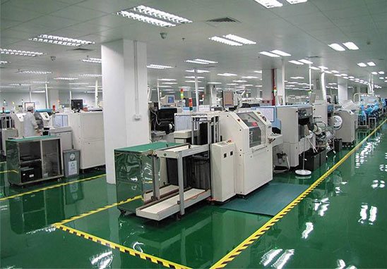
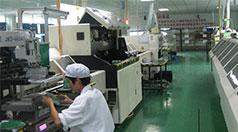
SMT Assembly Capability
1. The largest board: 310mm*410mm (SMT);
2. Maximum board thickness: 3mm;
3. Minimum board thickness: 0.5mm;
4. The smallest Chip parts: 0201 package or parts above 0.6mm*0.3mm;
5. The maximum weight of the mounted parts: 150 grams;
6. Maximum part height: 25mm;
7. The largest part size: 150mm*150mm;
8. Minimum lead part spacing: 0.3mm;
9. The smallest spherical part (BGA) spacing: 0.3mm;
10. The smallest spherical part (BGA) diameter: 0.3mm;
11. Maximum component placement accuracy (100QFP): 25um@IPC;
12. Mounting capacity: 3 to 4 million points/day.
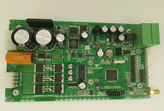
SMT Assembly Flow
1. Customer orders
Customers place orders according to their actual needs and put forward specific requirements and then PCBA manufacturer evaluates its own capabilities to see if it can complete the order. If the manufacturer determines that it can complete the order within the expected time, then the two parties will negotiate to determine the production details.
2. Customers provide production materials
After the customer decides to place an order, he provides a series of documents and checklists to the PCBA manufacturer, such as PCB electronic files, coordinate files, and BOM lists required for production, which are all required.
3. Purchase raw materials
PCBA manufacturer purchases required raw materials from designated suppliers according to the documents provided by customers.
4. Incoming Material Inspection
Before PCB Assembly, all raw materials to be used are subjected to strict quality inspection to ensure that only they are qualified and then put into production.
5. PCBA production
During PCB Assembly, in order to ensure production quality, whether it is SMD or solder production, manufacturers need to strictly control the furnace temperature.
6. PCBA test
The PCBA manufacturer conducts strict PCBA test, and the PCB boards that pass the test are delivered to the customer.
7. Packaging after sale
After PCBA processing is completed, the product is packaged and then delivered to the customer to complete the entire PCBA Assembly work.